HOME CALENDAR OF EVENTS LOCOMOTIVE TYPES NEWS SIGNALING DCC MODULAR LAYOUT MEMBERS MEMBERSHIP APPLICATION OUR HISTORY LAYOUT TOUR FALLEN FLAGS CONSTITUTION
![]()
![]() RR&Co & SE8C
RR&Co & SE8C ![]()
![]()
ATSF
Dual Track ABS Signaling ![]() Signaling
overview
Signaling
overview ![]() How we did it
How we did it ![]() Signaling
on our Modular Layout
Signaling
on our Modular Layout ![]()
Using the SE8C with
Railroad & Company’s
(RR&Co.) TrainCointroller
(TC)
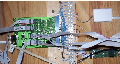
When crimping the connector, there are three things to observe carefully. First, the connector must be absolutely square with the cable. Second, the connector has an indent to identify pin 1. Make sure that coincides with the red strip. Third, use an even pressure, but not too much, to squeeze the connector closed. Channel locks work well if you set its closed width to the width of a closed connector. Failure to do so may result in a bad crimp causing one or more aspects of a signal to not work, or you will break the connector while crimping. Test the cable with the test mast before installing. I recommend using the supplied strain relief at all connections. This will help secure the connection and prevent it from pulling apart.
In the above picture, a signal (1 of a possible 4) is wired to the High Common and the High Red, Yellow, and Green terminals. That is the B signal. Additional signals can be wired to the High Common and Low switched (C), Low Common and High Switched (A1), and Low Common and Low Switched (A2) outputs.
Remember to tell the SE8C whether you are using common anode or common cathode signals. You cannot use both on the same drivers, but you can divide drivers 1-4 and 5-8 to be one or the other if you happen to have both types of signals and wish to use them all. It is generally good practice to use all of the same type.
|
|
|
This is an SE8C as mounted under one of our modules. The edge connector pins are wired to a terminal strip next to it. It then can be easily wired to other components, and allows for easy troubleshooting when needed. This should be done with all boards that use the edge connectors. In our modular setup we then just plug in the ribbon cables and Loconet and are ready to go. Power to the board is supplied by a PS12. |
The turnout motor outputs could also be used to control semaphore signals. When set up that way, the SE8C will send a command to the motor to move to any one of 3 positions; full left, center, or full right to simulate the three aspects of a semaphore signal. So if that's the era you want to signal, it can handle that too.
The SE8C has no onboard logic to set signal aspects. That logic must come from another source that issues programmed switch commands based on the situation. That can come from another board, a throttle, or a computer. The board comes with the default switch numbers 257 through 320 and the 4th aspect defaults to a flashing Yellow. The default turnout addresses are 1 through 8. The sensor inputs are 1,1 through 1,8. Setting the board ID to a number other than the default 1 will change the signal address ranges, the sensor addresses, as well as the turnout addresses, though there is the option ro set the signal addresses independant of Board ID. The fourth aspect can also be programmed for flashing green, flashing red, or blank for approach lighting*) Each signal head uses two switch numbers. After the signals are set up, you control the lights with switch commands**. This is demonstrated very well in the manual when you do the Pre-installation Testing. For example, Plant 1, Signal A1 will turn Green if you send a closed command to switch 257. If you send a thrown command to switch 257 the signal will turn Red. If you send a closed command to switch 258 (next in line) that same signal will turn Yellow. A thrown command to switch 258 will flash Yellow (default). Plant 1, Signal A2 uses switch numbers 259 & 260. B uses 261 and 262 and C uses 263 and 264. Plant 2 uses the next 8 switches and so on.
* Approach lighting, by extinguishing the lights when no train is present, is used by railroads to extend the life of the lamps. They "come alive" when a train enters a block controlled by a signal. The SE8C can be configured to duplicate that situation.
** Switch commands: An accessory address being sent a command to either throw or close. Signals, turnouts, and any other accessories controlled by a stationary decoder share a range of addresses, up to 2048. No two accessories can have the same address, so be careful when assigning addresses to your accessories. Loco addresses are handled independently from accessory addresses, so there is no conflict between them. Loco addresses can go up to 9983.
Train
Controller® and the SE8C
Step by step for one signal example:
First set up your Switchboard with your track, turnouts, and detectors. After you have this part working to your satisfaction, add a two, three, or four aspect signal as appropriate for each situation on the Switchboard. .
(A note on names. Train Controller uses the name of a switchboard element when referring to it in the properties or operations of another element. When you first add an element, such as a turnout or signal, TC names it based on its location on your switchboard. If you don't assign a new name that you can remember, and you have a number of them, you will have a difficult time figuring out which one to refer to later.)
Next, click on the Connection Tab. Make sure the system is Digitrax Loconet. Next enter the address. BE CAREFUL. This number must be the FIRST switch number of the SE8C signal head you are trying to control. For example, if your SE8C is board 1 and your 10-wire ribbon cable is plugged into DRV1 and you are using signal A1 of that plant, enter address 257. TC will automatically know that address 258 belongs here also. NEVER enter the second address of a signal. If your 10-wire ribbon cable is plugged into DRV 6 and you are controlling the B signal, enter 301. All these addresses are on page 7 of the SE8C manual. For higher Board IDs, just add 64 to the number for each board numbers above 1.
If
you wish, click the test signal until it turns Red and
check the box
|
Green |
C | C | ||
|
Red |
T | C | ||
|
Yellow |
C | T | ||
|
White |
T | T |
For Green, we want the first switch to be closed and the second switch blank.
First switch is already closed so click on the second C to blank it out.
For Red, click on the C and blank the second switch out.
| For | Yellow | , click on the first C to blank out the first switch. |
For , blank out the first T and change the second T to C by clicking on the button where the C is supposed to be.
| When you are done, it should look like this: | 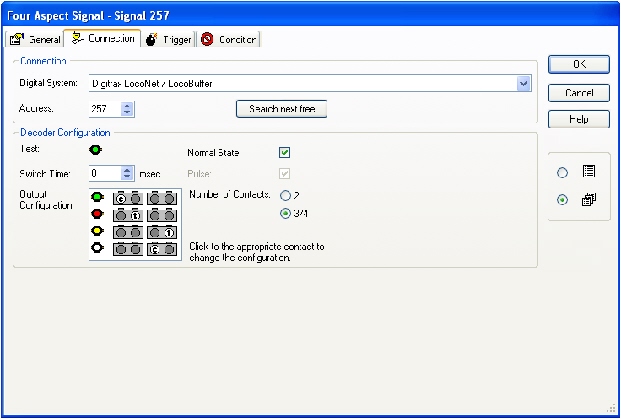 |
Do the preceding for each signal you want on the layout. Be careful of the addresses.
The next section is on controlling all these signals from within TC.
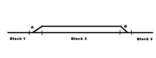
The triggers for each signal are now incorporated into the signal properties. Since you can have and/or statements together, it simplifies everything. You can also have the signal aspect displayed differently for the same basic conditions, but based on the direction of travel. For example, using the diagram below, an eastbound signal at turnout A would show yellow if both turnouts were aligned, block B was clear, and Block C was occupied with an eastbound train. However the same signal would show red under the same sensor conditions if the train in Block C was westbound. Therefore, you could have direction based logic for the signal to accurately show the proper aspect for all possible conditions. This is easily done in the properties.
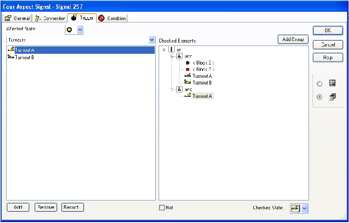
If using version 5.8 or later, the logic is setup as follows using this example:
We have a signal facing the points of turnout A
Under the Trigger tab, you select the conditions for each aspect, except the default, usually Red.
For Green, click Add Group. You will see an "&" appear in the right box.
Next select from the list of elements on the left those elements that would cause a Green signal, in this case Block 2 and Block 3 Unoccupied & Turnouts A & B Closed.
Next for Yellow. Select an "OR" group. With it highlighted, add another Group below it. Under this "&" Group select Turnout A Clear "&" Turnout B Clear "&" Block 2 Clear "&" Block 3 Occupied.
Go back up to the 1st "OR" Group and add another sub Group, again an "&"
Under that new Group select Turnout A Thrown. That completes the conditions for triggers.
Notice that the turnouts are NOT included in any of the detection blocks.
It would look like this:
You will notice that we didn't add any triggers for Red. The signal will then default to this if none of the other conditions apply.
This is a rather simple example. Your layout may have some more complicated situations. Just logically consider all the conditions that need to be true for each aspect of a signal and enter those. If you have a double headed signal, you would need to add two signals on your switchboard and enter the conditions for each one.
Normally, if the above track was a bi-directional mainline, you would have double headed signals facing the points of each turnout, plus a single head signal facing the frog on the mainline and the siding at each turnout, for a total of eight heads. That would take up two drivers of the SE8C. The logic gets a bit more complicated for bi-directional traffic, as direction of travel would come into play.
The time invested is well worth it if you want to have accurate working signals on your layout. As time went on, I found a need for more signals, particularly at an area where a double track mainline met the throat of a classification yard. There are six signals located there. As a result, the number of possible conditions was multiplied.
Photos and text on this site are © 1977 - 2018 Sheboygan Society Of Scale Model Railroad Engineers, Ltd. All rights reserved.
Updated: Saturday, August 18, 2018