HOME CALENDAR OF EVENTS JUST RAILROADS LOCOMOTIVE TYPES NEWS SIGNALING DCC MODULAR LAYOUT MEMBERS MEMBERSHIP APPLICATION PRESS COVERAGE CASEY AT THE THROTTLE WEBRINGS - LINKS OUR HISTORY LAYOUT TOUR FALLEN FLAGS CONSTITUTION
ATSF
Dual Track ABS Signaling ![]() Using RR&Co with an SE8C
Using RR&Co with an SE8C ![]() How we did it
How we did it ![]() Signaling
on our Modular Layout
Signaling
on our Modular Layout ![]()
Signaling Overview
|
To start with, the layout must be divided into Signaling Blocks. Signaling Blocks can be divided into multiple Detection Sections if desired. Your level of signaling will determine how many Detection Sections will be in each Signaling Block. Before you can decide how to divide your layout up into Detection Sections, you have to decide what kind of signaling you want. There are probably more types of prototypical signaling than there are railroads. Considering that each road's signaling standards have evolved over time, each road could have had several different signaling methods over the years. Further, as roads merged, they could have different signaling methods on different sections of trackage - only to evolve once again into something more consistent. If you want absolute prototypical signaling for your layout, you first have to determine which era you're modeling, which stretch of track on which road you're modeling, then research the historic records to see how they signaled that stretch of track in the year you're modeling. After that, you'll have to use modeler's license to extrapolate the real thing down to what makes sense for a scaled-down, limited-mileage, model. Most people prefer to not go to that much trouble. They opt for something sort of prototypical - a signaling method that makes more sense for the model railroad than for the real thing. To get started, you need to determine what kind of signal heads your railroad would be using. |
|
There
are several different prototypical signal heads used by various roads
over the years. First is the three-light vertical signal, as shown at
right
|
|
A
variation of this, used by some roads, has a hood that protects the
lenses from glare, as shown at left
|
|
These
signals usually had the green light on top, red on bottom, with yellow
in the middle - just the opposite of three-light traffic signals.
|
|
Sometimes
a two-light version, as shown at right, is all that's needed, usually
for a second head to indicate a second route that is available at a
turnout.
|
|
Another
variation of the three-light signal is the 3-light searchlight signal,
shown at left. It has the green and yellow on top, with red on bottom.
|
|
A
variation of this is the multi-color single light target, illustrated
at right. The real ones had a mechanical method behind the shield that
changed lens colors. Model signals use bi-color LEDs that can produce
all three colors through electronic wizardry.
|
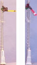 |
In the early days, signaling was done with semaphores, shown at left. These were indicators at the top of a mast that moved up and down according to the conditions of the track ahead. There were typically two types: upper quadrant, shown at left in the picture, and lower quadrant, shown at right. Upper quadrant semaphores move the arm from straight out to the up position, while lower quadrant semaphores move the arm from straight out to the down position. |
|
Semaphores
also had colored lenses in the head that moved in front of a light with
each position - providing an indication that could be more easily seen
at night.
|
|
Because
the semaphore's mechanics required so much maintenance, some roads, PRR
for one, replaced them with lighted signal heads (shown at right) that
mimicked the semaphore. The three vertical lights would be on to
indicate a straight up and down semaphore, three across would indicate
the semaphore sticking straight out, and the three angled across would
indicate the mid position.
|
| A variation
of the PRR signal, shown at
left, was used by the B&O railroad. Still another variation was
used extensively by the Norfolk and Western, some of which are still in
use. |
|
Dwarf signals, shown at right, are usually used in yards and usually have two or three lights. The two- light version may be red and green or red and yellow. |
|
Once you've determined which type of signals you'll be using, you need to know a little bit about why signaling is used and how it works. To start with, signaling is primarily used to provide the engineer with information about the trackage ahead - whether or not there's a train in the next two or three blocks. A train moving down the track will change signal colors behind the train for trains following, and ahead of the train facing the other way if it's a stretch of bidirectional track. Needless to say, your trackage will dictate how your signaling should work if you plan to use signaling during operating sessions for their prototypical purposes. Additionally, signals can be used for speed control and to let the engineer know which way a turnout is facing. With all that said, let's describe some signaling methods. There are three basic signaling methods: ABS (Automatic Block Signals), APB (Absolute Permissive Block control), and CTC (Centralized Traffic Control). Coupled with all the variations and options, you could have hundreds of different scenarios. We'll start by describing the basics of ABS, then show variations and options along the way. There are two general places where signals are placed: at turnouts, and along long stretches of track so one train won't follow another too closely. Signals along long stretches of track tell engineers whether or not there is a train coming within the next two or three (depending on the signal system) blocks. |
|
With
no trains present, all signals are green in both directions (as shown
at left) indicating clear trackage.
|
|
An
East bound train in block #3, for example, causes the East bound
signals going into blocks 2 and 3 to be yellow, and red, as shown at
right.
|
|
|
The East bound yellow signal lets an engineer in block #1 know that block #2 is clear, but that there is a train in block #3. The East bound red signal lets an engineer in block #2 know that there is a train in block #3. |
|
|
Variations: Some roads have what's called approach lighting - the signals are all off until a train approaches, at which time the signal comes alive. This was done to extend lamp life. Some roads also have a blinking yellow one block before the solid yellow. That lets an engineer know that there are two clear blocks ahead. The old ATSF was one such road. Lastly, while red means stop with most roads, it means stop then proceed slowly with some. |
|
East bound signals ahead of the train are green all the way to the next place where trains can pass each other - assuming there are no trains until then. But what keeps a West-bound train from going right by the passing siding to have a head-on collision (corn-field meet)? Under normal ABS rules, nothing. But with a feature called tumble-down, used in APB signaling, West bound signals ahead of the East bound train will be red all the way to the next passing siding. Signals at turnouts generally have two heads: a three-light head to indicate the condition of the track ahead, and a two-light head to indicate which route the turnout is set for. The bottom head in the illustration below is red, indicating that the turnout is set for the mainline, and the top head is green showing that the mainline trackage ahead is clear. |
 |
|
Note that the turnout is a detected block all by itself. This is mostly for CTC systems (discussed later), but can also be included in ABS/APB signaling. Even so, the signal at the turnout is also for the next block ahead, not just for the turnout itself. Unless using CTC, the position of the turnout affects the signals. Without a train present, on our example with the turnout set for the mainline, the West bound siding signal would be red while the West bound main line signal would be green. Speaking of CTC (Centralized Traffic Control), let's discuss that a little right now. While ABS and APB signaling is done automatically by electronic controls, CTC is a system whereby a person controls the signals and turnouts from a centralized location - sort of like the control tower at an airport. |
|
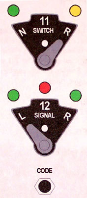
Typically, the "control tower" would have a schematic of the entire trackage that is controlled there. And there would be a pair of switches and a button (shown at the right) at each turnout on the schematic. The upper switch controls the turnout. "N" is for Normal (main line traffic) and "R" is for Reverse (siding traffic). The lower switch controls the signals. "L" clears the way for Left bound traffic and "R" clears the way for Right bound traffic. The position in the middle sets signals red in both directions. The code button tells the system to execute the settings. This allows the controller to preset the switches, but not execute until the trains have cleared. This could be set up without any special electronic equipment if you're very good at figuring out relays, wiring, and the such. But the addition of electronic boards to do this for you can relieve you of all that meditation and frustration. |
 |
|
CTC is obviously a manual operation - requiring someone to sit at the CTC board during the whole time anyone is running trains. However, with DCC, turnouts can be set up for CTC control during operating sessions, and DCC control when a couple of people are just running trains for fun. It can be set up so DCC control is locked out during operating sessions, or left on (relying upon everyone's integrity to NOT control turnouts with DCC during the session). As you can see, a lot of thought has to
go into block detection and signaling for it to all happen as it
should. Because getting every aspect of prototypical signaling right
can be quite complex, many people choose to signal their layouts the
way "they" choose for it to be. This is OK - most people won't know the
difference anyway. |
Updated: Friday, August 17, 2018